Modeling of Patch Antennas
Microstrip patch antennas are among the most common antenna types in use today, particularly in the popular frequency range of 1 to 6 GHz. This type of antenna had its first intense development in the 1970s, as communication systems became common at frequencies where its size and performance were very useful. At the same time, its flat profile and reduced weight, compared to parabolic reflectors and other antenna options, made it attractive for airborne and spacecraft applications. More recently, those same properties, with additional size reduction using high dielectric constant materials, have made patch antennas common in handsets, GPS receivers and other mass-produced wireless products.
Examples of Patch Antennas
For antenna investigations several factors should be studied: antenna input impedance and matching with feeding line, radiation pattern and antenna polarization. Since usually only few first resonances of antenna are of most interest for simulations of patch antennas Green function approach within the MoM solver TriD can be effectively used. Examples of Patch Antenna modeling within EMC Studio are presented.
Structure of microstrip patch antenna can vary from the very simple, like rectangular patch, to the complicated antenna arrays consisting of different shaped elements. In the EMC Studio Models library several models of patch antenna are available.
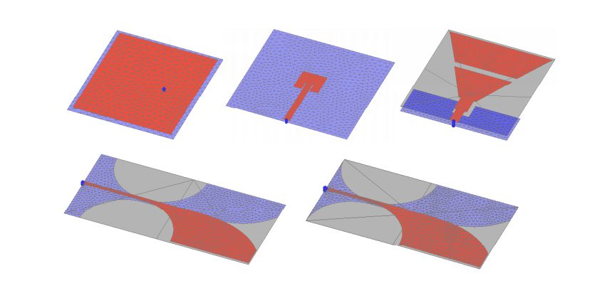
For each antenna modeling of dielectric substrate is performed using Finite Dielectric Substrate.
Rectangular Patch Antenna
The most simple and known patch antenna is a Rectangular Patch Antenna. Antenna is usually designed for operation at defined frequency and its dimensions are calculated as a half-wavelength.
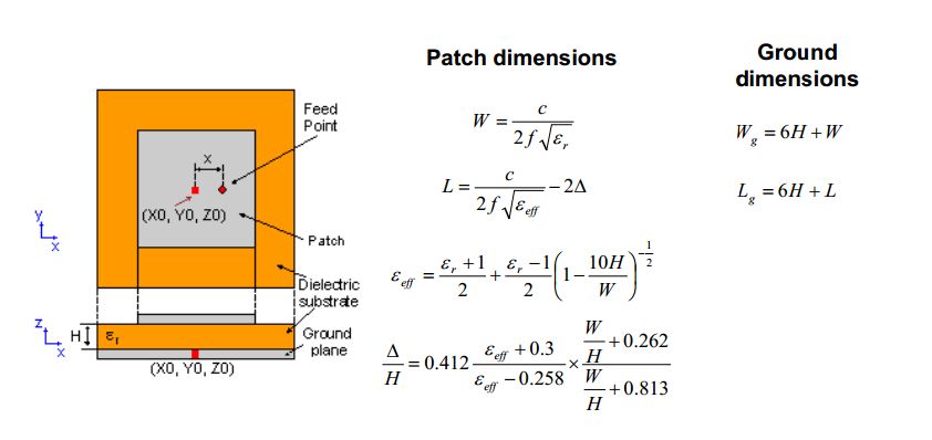
Location of feeding point is selected depending on feeding line impedance. The feed point must be located at that point on the patch, where the input impedance is equal to impedance of feed line for the resonant frequency.
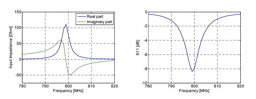
Simulations are performed for patch antenna with resonance at 800 MHz and feed line impedance 50 Ohm. Dielectric substrate between patch and ground plane has thickness 1.6 mm. Dielectric properties are characterized by relative permittivity µr=2.55 and dielectric loss factor tanґ=0.
Antenna input impedance and reflection coefficient with respect to feed line Z0=50 Ohm are shown in the following graphs:
Surface current distribution and antenna gain at frequency 800 MHz are shown in the following pictures:
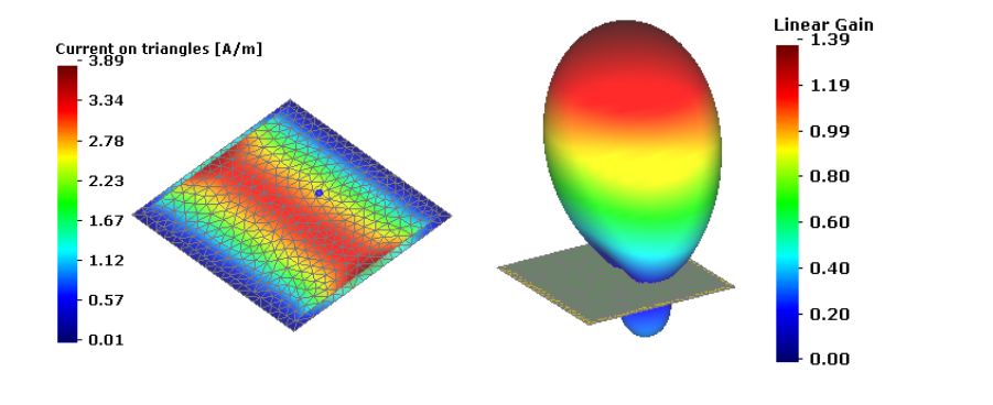
Two-dimensional plot of antenna gain at frequency 800 MHz in the YZ plane and maximum antenna gain for the frequencies around resonance frequency 800 MHz and shown in following figures:
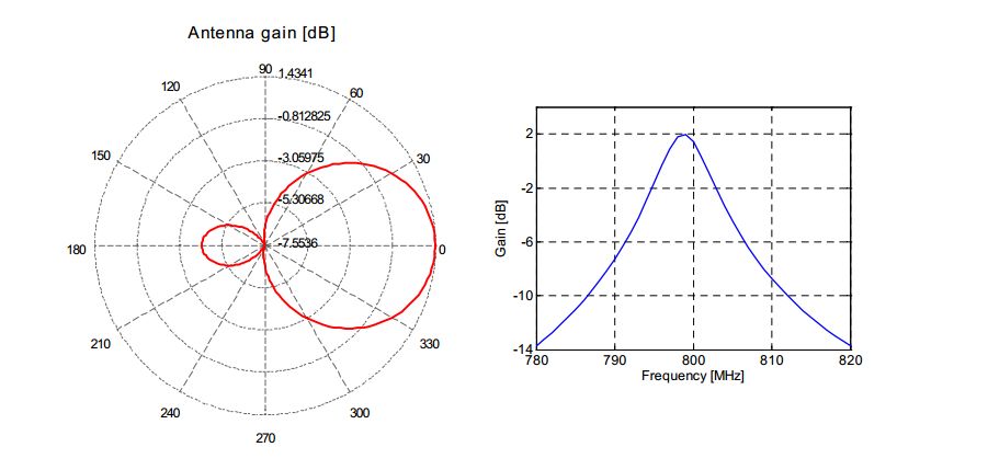
It can be seen that maximum gain is about 2 dB.
Antipodal Vivaldi Antenna
Another example of patch antenna is Antipodal Vivaldi antenna. Antenna is characterized by quite wide bandwidth due to its design.
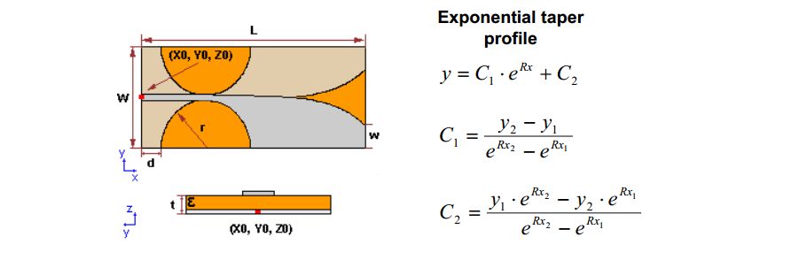
The top and bottom layers show the exponential taper profile, which is defined by the opening rate R and the two points P1 (x1, y1) and P2 (x2, y2) (first and end points of the exponential taper).
Simulations are performed for the antenna model characterized with the following parameters:
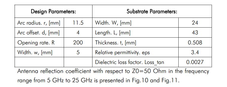
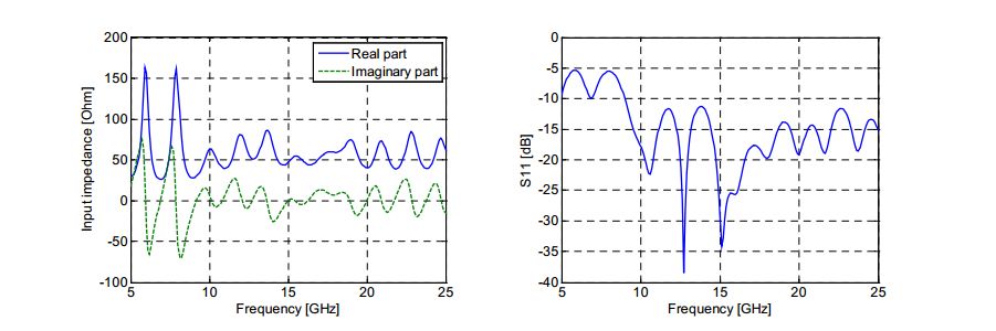
Antenna gain maximum in the same frequency range and radiation pattern for frequency 15 GHz are presented in following graphs:
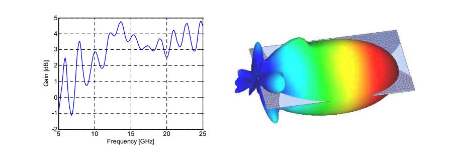
It can be seen that maximum antenna gain is about 4.75 dB
Conclusions
- Within EMC Studio patch antenna simulations can be performed using
- Green function approach for dielectric substrate modeling
- Both antenna input parameters and radiation pattern can be calculated