Signal Integrity in CAN
A modern automobile may have as many as 50 electronic control units (ECU) for various subsystems, which must be investigated onto EMC problems such as crosstalk and signal integrity.
One of the known vehicle buses standard for data transfer is CAN bus system. Controller “area network (CAN) is a multiplexed wiring system used to connect intelligent devices such as Electronic Control Units (ECU’s) onto vehicles, allowing data to be transmitted in a low-cost and reliable manner.
Within EMC Studio currents and voltages are calculated in time domain for CAN system transceiver and receiver.
Problem Definition
CAN device in addition to the main part usually contains countermeasure modules, which are stabilization network and common-mode choke. Stabilization network smoothes CAN signal by removing undesirable ringing. Common-mode choke usually consists of coupled inductances, and this module cancels out unwanted common-mode currents in the system, decreases level of radiation and improves immunity.
TWP cable connecting CAN devices is located above the ground plane. Currents and voltages are calculated in time domain for CAN system transceiver and receiver.
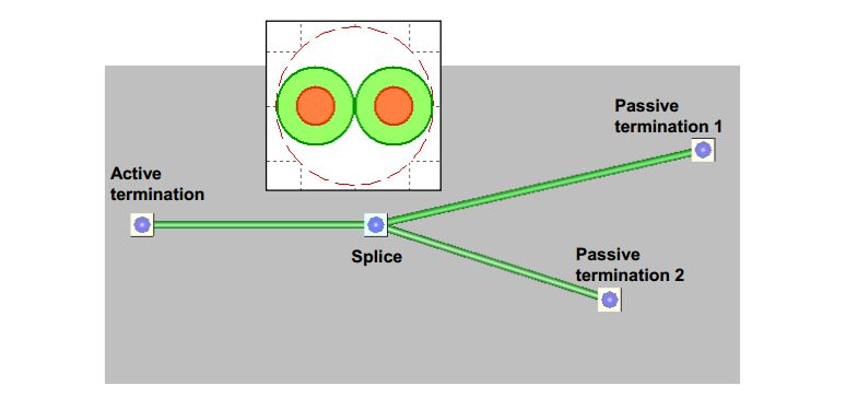
Terminating devices of cable system used in model are shown in the figures below:
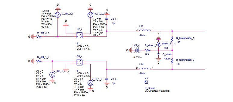
В Model 33 Ohm CAN Driver (Active termination)
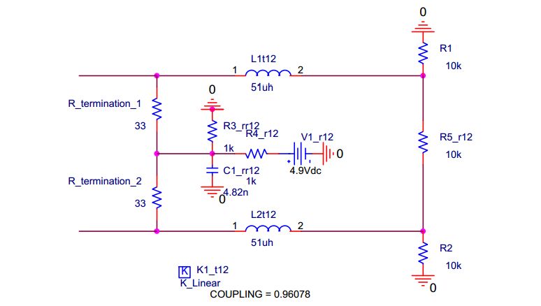
Model 1300 Ohm CAN Receiver (Passive termination)
Numerical Results
Voltages in CAN terminations are presented in the figures below.
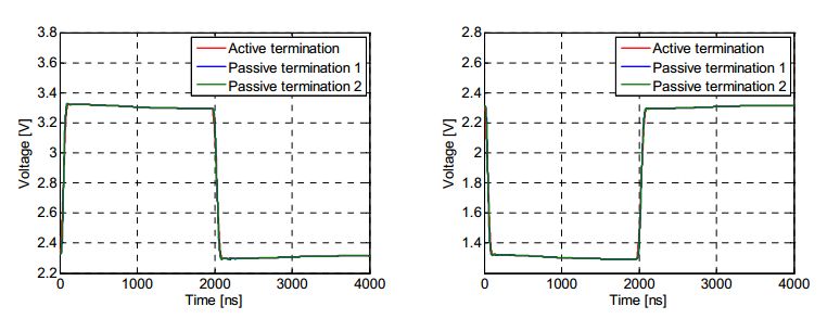
Voltages at high and low pins respectively
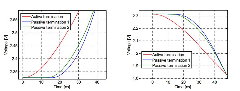
Zoomed view of voltages at high and low pins respectively
Conclusions
- Within EMC Studio Hybrid Analyses Type non-linear harness system such as CAN bus systems can be investigated
- The Signal Integrity problem was investigated in CAN system