Simulations with Aircraft Environment
Introduction
EMC Studio provides comprehensive analysis capabilities of EMI/EMC problems arising in aerospace systems. This includes: antenna to antenna coupling analysis; antenna placement considerations; lightning interaction with aircraft; analysis of cross talk problems between cables; field scattered analysis; EMI/EMC of printed circuit boards in aerospace systems; electromagnetic shielding analysis.
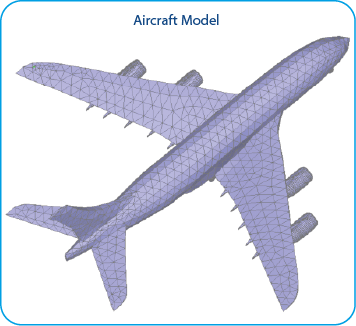
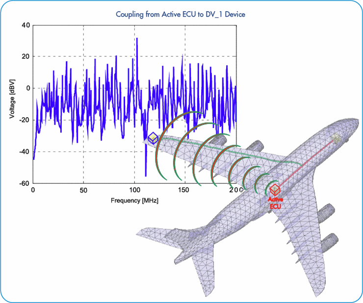
This application note considers aircraft model with cable system passing along its floor and left wing. Coupling from Active ECU into passive device is demonstrated. Simulations are performed in frequency range from 1 MHz to 200 MHz.
Simulation Model Description
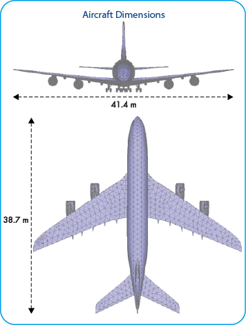
Aircraft model (41.4 mВ x 38.7 m) with cable system passing along its floor and left wing:
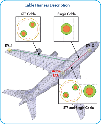
Aircraft cable harness parameters are the following:
- Cable system consisting of TWP with solid copper shield (STP) and single cable is passing along the aircraft door and left wing
- Length of STP is 30 m
- Length of single cable is 12.9 m
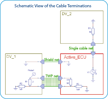
- Coupling from Active ECU into device DV_1 is observed in frequency range from 1 MHz to 200 MHz
Results
Voltage coupled at Probe 1 of device DV_1 from Active ECU at frequency range 1 – 200 MHz is shown below:
Conclusions
Modeling of complex cable bundles in aircraft environment can be effectively done with help of EMC Studio tools. Integrated Hybrid solvers provides fast and accurate results for cross talk, susceptibility and radiation problems arising in aerospace systems.

