Modeling of 3D Layout Influence on LC Filter Performance
Introduction
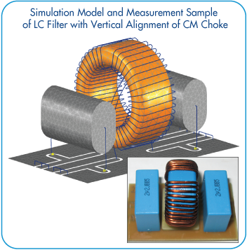
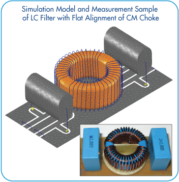
This application note demonstrates influence of 3D layout on LC filter performance. Two models of LC filter with vertical and flat alignment of CM choke are considered. Full wave Method of Moments (MoM) is applied. Simulations are performed in the frequency range from 10 kHz up to 100 MHz and are in a good agreement with measurements.
Simulation Models and Measurement Samples
Two variants of the filter with different placement of components are shown below, as well as their 3D models:
Filter Components Modeling
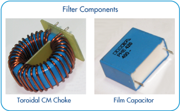
Filter components considered in three-dimensional model are two voluminous film capacitors and toroidal CM choke. All components are arranged on a printed circuit board.
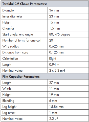
Toroidal core is modelled in MoM using surface integral approach and is represented by bulk dielectric object described by its outer surface (discretized mesh contains about 2788 triangular elements). Winding is represented by 1528 wire segments. This approach gives possibility to consider directly influence of frequency dependent complex material parameters of ferrite material on impedance of coil, as well as the influence of capacitance between windings and capacitance of windings to core.
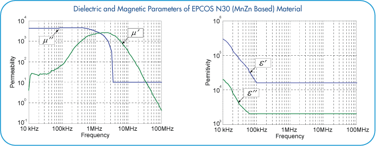
Dielectric and magnetic parameters of EPCOS N30 (MnZn based) material were used for modeling of toroidal choke ferrite core.
Frequency dependence of electric and magnetic properties of EPCOS N30 MnZn-based ferrite material is shown below:
Comparison of Measured and Simulated Characteristic of Filter
Comparison of measured transmission coefficients with simulated results for both filter models is shown below. Simulation results are in good agreement with measurements.
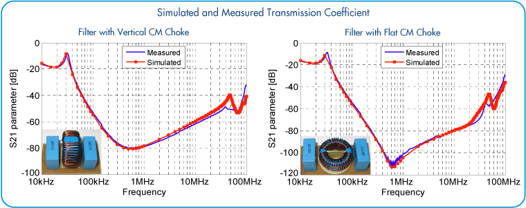
- Measurements of transmission coefficients for both filter samples were performed using EMI test receiver HP8546A
- Simulations were performed with MoM based TriD solver in frequency range from 10 kHz up to 100 MHz
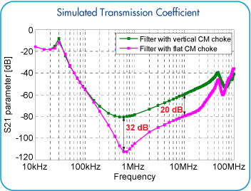
The plot on the left shows comparison of transmission coefficients for two filter models with vertical and flat alignment of the CM choke. From the obtained results it can be seen that at frequencies above 400 kHz performance of the filter is affected by placement of components. Difference in transmission coefficient for filters with flat and vertical CM chokes reaches 32 dB at 600 kHz and is about 20 dB at 10 MHz.
Analysis of Radiated EM Fields
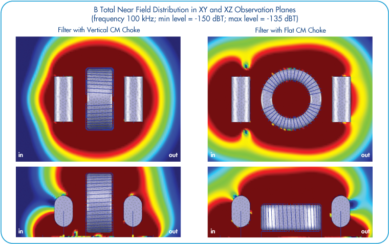
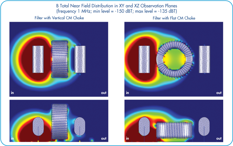
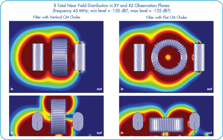
Observation of radiated EM field distribution around filter components can deliver important information about coupling between components and helps in optimization of filter layout or its placement relative to other electronic devices around.
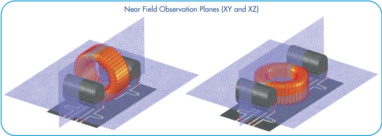
Observation of near fields is performed on two near field areas located in XY and XZ planes.
B total near field distribution plots for several selected frequencies (100 kHz, 1 MHz, and 45 MHz) are presented below. Both filter models with vertical and flat positioning of CM choke are considered.
Conclusions
- EMCoS Studio provides advanced construction tools and comprehensive simulation methodology for accurate modeling of EMC/EMI filters and investigation of the influence of 3D layout on overall filter performance, including analysis of radiated EM fields around filter components
References
- A. Gheonjian, B. Khvitia, D. Yeremian, Z. Kutchadze, R. Jobava, X. Bunlon “FULL WAVE MOM SIMULATIONS OF EM INTERACTIONS IN EMC FILTERS FROM 10 KHZ TO 50 MHZ”, 17th International Symposium on ElectroMagnetic Compatibility (CEM 2014), 1-3 July, 2014