Modeling of PCB with IC Package
Introduction
This application note demonstrates modeling of PCB controller with IC package connected to WiFi antenna and signal processing board. S-parameters of multiple ports of the system are extracted in order to show how overall system performance can be estimated in EMCoS Studio environment.
Simulation Model Description
Detailed system configuration is shown below. WiFi antenna is connected to PCB controller by coaxial cable. Two boards are connected via bended flex cable. The models of PCBs and antenna are imported from ODB++/CAD file formats. The controller board contains IC package that consist of ground paddle, silicon die, leads and bondwires. Total dimensions of the model is about 15 cm.
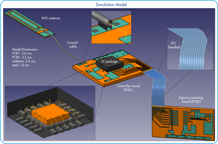
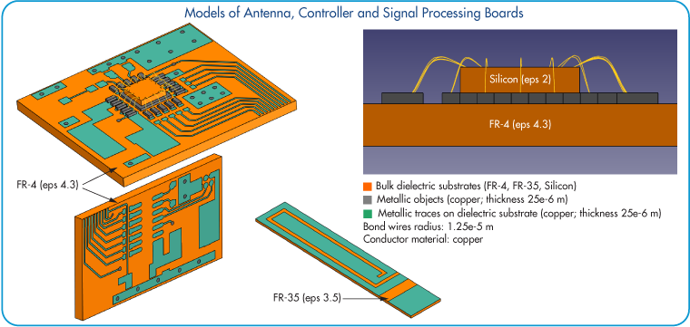
Physical properties of the model are shown below. FR-4, FR-35 and silicon dielectric materials are used for PCBs, antenna and IC package substrates correspondingly. The copper is used as a conductor material.
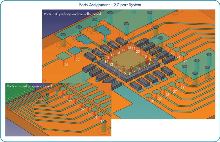
Ports Definition in IC Package and PCBs
To extract S-parameters and estimate system performance 37 ports are defined on different parts of the model. Twenty ports are assigned between metallic pads and ground paddle of the IC package. The remaining ports are assigned between metallic traces and ground layer.
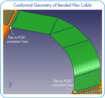
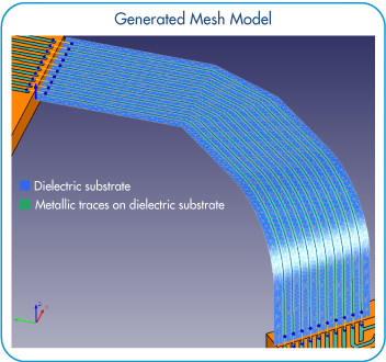
Flex Cable Modeling
Geometry of the bended flex cable was imported from CAD file format. Generation of the physical model was performed with help of special conformal structures construction tools. These tools allow flexible definition of the narrow metallic traces projected on conformal cable surface with dielectric properties. Automatic discretization of the cable structure takes just a few seconds and produces mesh model for simulation.
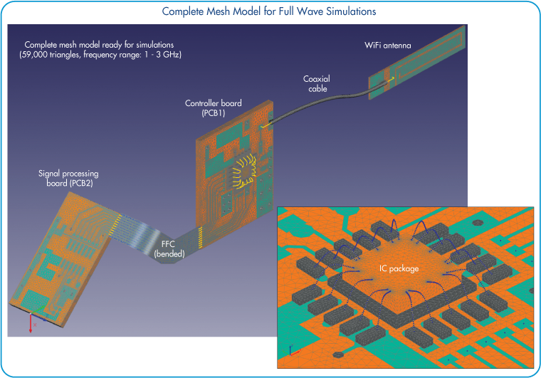
Full Wave Simulation Model
Complete mesh model for full wave simulations contains 59 000 triangles. Adaptive meshing was used to minimize number of triangles while preserving accuracy of smaller geometry parts. The simulation was done in the range from 1 GHz up to 3 GHz.
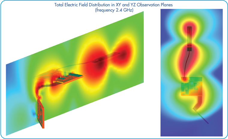
Simulation Results
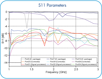
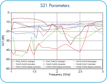
S-parameters for ports assigned to IC package, signal processing and controller board are presented on pictures below:
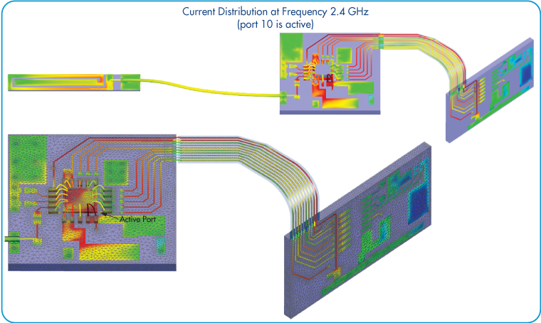
Current distribution plot illustrates the case when port 10 is active. The distribution corresponds to the frequency of 2.4 GHz.